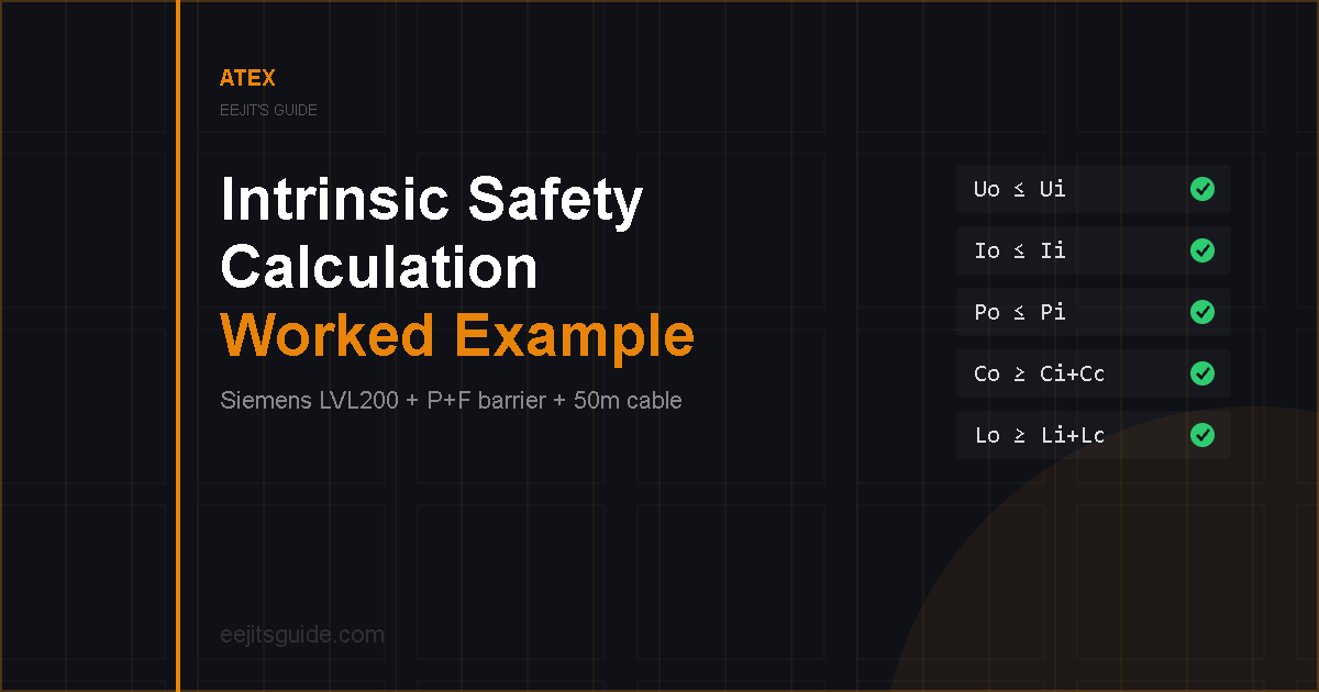
Intrinsic safety calculations look fairly simple when they are reduced to five equations.
Check the voltage. Check the current. Check the power. Check capacitance. Check inductance.
Done.
Unfortunately, the maths is usually the easy bit.
The more important part is making sure you have the correct equipment, the correct certificate, the correct certificate issue, the correct table, the correct units and the correct cable information before you start entering numbers into a spreadsheet.
In this article, I’m going to work through a practical intrinsic safety example using a Siemens SITRANS LVL200 level switch and a Pepperl+Fuchs galvanic isolator.
The example:
- High-level switch on an ethanol tank
- Field device installed in a Zone 1 hazardous area
- Siemens SITRANS LVL200
- Part number: 7ML5747-4CC47-3AA0-Z
- Pepperl+Fuchs KFD2-SR2-Ex2.W switch amplifier
- Barrier installed in a non-hazardous area panel
- 50 m instrument cable
Important disclaimer:
This is an educational worked example, not a design approval or hazardous-area certification.
Always check the exact equipment variant, current manufacturer certificates, certificate supplements, special conditions of use, hazardous-area classification, cable manufacturer data and applicable project and regulatory requirements.
A competent person should approve the actual intrinsic safety loop before installation or commissioning.
What Are We Trying to Prove?
The basic purpose of the intrinsic safety calculation is to prove that the energy available from the associated apparatus cannot exceed the limits of the field device and that the external capacitance and inductance remain within the permitted values.
For a basic entity-parameter assessment, we are normally checking:
Io ≤ Ii
Po ≤ Pi
Co ≥ Ci + Ccable
Lo ≥ Li + Lcable
If you’re new to intrinsic safety, you can read my broader guide first:
Intrinsic Safety Explained: Ex i, Barriers and IS Circuits Made Simple
.
Before We Start: Does This Equipment Actually Need to Be ATEX?
This section is aimed particularly at customers, project managers and anyone writing specifications.
Before spending money on intrinsically safe equipment, barriers, certificates and hazardous-area engineering, ask a very basic question:
Does this equipment actually need to be installed in a hazardous area?
I’ve seen projects where hazardous-area requirements are assumed from the start, only for the actual classification to be unclear or completed much later.
I’ve also experienced the opposite.
A project starts with the understanding that an area is not hazardous. Design progresses, equipment gets selected, procurement starts and then later someone produces the hazardous-area assessment and announces that parts of the installation are classified.
That can become expensive very quickly.
You’re potentially looking at:
- Redesign
- Re-procurement
- Replacement equipment
- Reinstallation
- Additional inspection
- Recommissioning
- Extra engineering hours
- Teams returning to site after they thought the job was finished
Any money that appeared to be saved by delaying the hazardous-area work can disappear very quickly while everyone tries to finish the project.
Get the HAC Documentation Done
If hazardous areas are possible, get the hazardous-area classification completed early and make sure the HAC drawings are kept current.
Know where the Zones actually are.
Then specify the equipment to suit the classified area.
Don’t simply fill an entire project with expensive Ex equipment because it feels safer.
More certification is not automatically better engineering.
Old Standards Aren’t Automatically Wrong
Another frustration of mine is being referred to an old company specification as though the fact that it exists means every requirement in it should remain forever.
Sometimes the document was written decades ago.
That doesn’t automatically make it wrong.
But it should probably make someone ask:
When was this last technically reviewed?
The equipment may have changed. Technology may have changed. The site may have changed. The applicable standards may have changed. The people who originally wrote the document may no longer work there.
Yet requirements can survive because:
“That’s how we’ve always done it.”
My slightly ridiculous example:
In the 1990s, children were constantly told not to speak to strangers.
Now people upload half their lives to the internet and happily let strangers from the other side of the world comment on it.
Things change.
Engineering changes as well.
If a company standard says the inside of every control cabinet must still be orange because somebody specified it 30 years ago, maybe there is a valid reason.
But somebody should at least know what that reason is.
The same applies to specifying Ex d panels for everything.
If Ex d is genuinely required, use it.
If another protection concept or modern system architecture satisfies the actual requirement more efficiently, it is worth considering.
Old does not mean wrong.
But “we’ve always done it that way” isn’t much of an engineering justification either.
The Equipment in This Example
Siemens SITRANS LVL200
The field device in this example is:
Siemens SITRANS LVL200 – 7ML5747-4CC47-3AA0-Z
We are using it as a high-level switch on an ethanol tank within a Zone 1 hazardous area.
The certificate used for this example is:
PTB 17 ATEX 2006 X – Issue 0
The certification covers different installation arrangements and EPLs, including markings within the LVL200 family such as:
II 1G / 1/2G / 2G Ex ia IIC T6…T1 Ga / Ga/Gb / Gb
The exact marking applicable depends on how the equipment is installed and the conditions stated in the certificate.
Pepperl+Fuchs KFD2-SR2-Ex2.W
The associated apparatus in the safe-area panel is:
Pepperl+Fuchs KFD2-SR2-Ex2.W
For this UK example, the certificate being referenced is:
CML 21UKEX2786 – Issue 0
The intrinsically safe circuit is marked:
II (1) G [Ex ia Ga] IIC
The square brackets are important.
They indicate that the intrinsically safe circuit from the associated apparatus can be suitable for equipment in the stated hazardous-area level, while the barrier itself is not necessarily installed in that hazardous area.
In our example, the barrier is kept in the non-hazardous area.
Step 1: Get the Certificate Data
Before doing any calculation, I like to put the important certificate values into a simple table.
| Parameter | P+F Barrier | Siemens LVL200 |
|---|---|---|
| Voltage | Uo = 10.5 V | Ui = 29 V |
| Current | Io = 13 mA | Ii = 116 mA |
| Power | Po = 34 mW | Pi = 841 mW |
| External capacitance | Co = 620 nF* | Ci = negligibly low |
| External inductance | Lo = 3 mH* | Li = negligibly low |
*For this worked example, I am using the IIC values from the certificate table applicable when external capacitance and inductance occur together.
Read the Correct Table
This is an important point.
The Pepperl+Fuchs certificate also contains larger values for external reactances when they occur individually.
For IIC, you may see values such as:
- Co = 2.41 µF
- Lo = 210 mH
It would be very easy to find those values, put them into an IS spreadsheet and move on.
But our cable introduces both capacitance and inductance.
For this example, the relevant certificate table gives:
- Co = 620 nF
- Lo = 3 mH
This is exactly why I don’t like blindly trusting a green PASS box.
The spreadsheet can only calculate using the information you give it.
If you use values from the wrong certificate table, the calculation can look perfect while the engineering behind it is wrong.
Step 2: Convert the Units First
Before comparing anything, I like to convert the values into consistent units.
This sounds basic, but it removes one of the easiest ways to make a serious mistake.
Examples:
- 841 mW = 0.841 W
- 34 mW = 0.034 W
- 620 nF = 0.620 µF
- 50 µH = 0.050 mH
Nano, micro and milli are very easy to mix up when you are copying values between certificates, datasheets and calculation sheets.
A decimal point can make a massive difference.
Is the value 993 W or 0.993 W?
A spreadsheet won’t know that you typed it incorrectly.
Step 3: Check Voltage – Uo ≤ Ui
The barrier maximum output voltage must not exceed the maximum input voltage permitted by the field device.
LVL200 Ui = 29 V
10.5 V ≤ 29 V
RESULT: PASS
The barrier cannot supply more voltage than the LVL200 is certified to accept.
Step 4: Check Current – Io ≤ Ii
Next, compare the maximum barrier output current with the permitted field-device input current.
LVL200 Ii = 116 mA
13 mA ≤ 116 mA
RESULT: PASS
Step 5: Check Power – Po ≤ Pi
Now check the maximum power.
LVL200 Pi = 841 mW
34 mW ≤ 841 mW
RESULT: PASS
Again, the available barrier output is below the permitted instrument value.
Step 6: Add the Cable
The cable is part of the intrinsically safe loop.
For this worked example, I am going to assume:
- Cable length = 50 m
- Cable capacitance = 200 pF/m
- Cable inductance = 1 µH/m
These are example cable values.
Do not copy them into a real calculation unless they actually match the cable being installed.
Use the manufacturer’s data for the real cable.
Step 7: Calculate Cable Capacitance
Cable capacitance is:
Convert that into more useful units:
The LVL200’s internal capacitance for the version without fixed cable is stated as negligibly low.
So for this example:
Step 8: Check Capacitance – Co ≥ Ci + Ccable
LVL200 Ci ≈ 0 nF
Cable capacitance = 10 nF
620 nF ≥ 10 nF
RESULT: PASS
Step 9: Calculate Cable Inductance
Using our assumed cable inductance:
Convert to mH:
The LVL200 Li is stated as negligibly low for the version without fixed cable.
So:
Step 10: Check Inductance – Lo ≥ Li + Lcable
LVL200 Li ≈ 0 mH
Cable inductance = 0.050 mH
3 mH ≥ 0.050 mH
RESULT: PASS
Final IS Calculation
| Check | Barrier | LVL200 / Circuit | Result |
|---|---|---|---|
| Voltage | Uo = 10.5 V | Ui = 29 V | PASS |
| Current | Io = 13 mA | Ii = 116 mA | PASS |
| Power | Po = 34 mW | Pi = 841 mW | PASS |
| Capacitance | Co = 620 nF | Ci + Cable ≈ 10 nF | PASS |
| Inductance | Lo = 3 mH | Li + Cable ≈ 0.050 mH | PASS |
Entity parameter result:
Using the certificate data and assumed 50 m cable values in this example, the five basic entity-parameter checks pass.
That does not mean we can stop checking.
The LVL200 Certificate Has an X – Don’t Ignore It
The Siemens certificate number ends in:
PTB 17 ATEX 2006 X
That X matters.
It tells us that there are specific conditions of use which need to be checked.
Section 17 of the certificate contains conditions relating to matters such as:
- Possible electrostatic charging of certain surfaces
- Installation considerations involving aluminium for particular equipment categories
- Equipotential bonding requirements for certain Category 1 and Category 1/2 arrangements
- Specific process temperature and pressure conditions for certain installations
Don’t see the X and just carry on.
Go to the section containing the specific conditions and decide which conditions actually apply to your installation.
Not every condition necessarily applies to every version or equipment category, but you need to check.
Temperature Class Isn’t Just a Label Either
The LVL200 certificate also shows how the permissible sensor and electronics temperatures relate to the temperature class.
For Category 2 equipment, for example, the permitted conditions become more restrictive as you move towards T6.
| Temperature Class | Measuring Sensor Temperature | Electronics Ambient |
|---|---|---|
| T6 | -40°C to +85°C | -40°C to +60°C |
| T5 | -40°C to +100°C | -40°C to +75°C |
| T4 | -40°C to +135°C | -40°C to +90°C |
| T3* | -50°C to +200°C | -40°C to +90°C |
| T2 / T1* | -50°C to +250°C | -40°C to +90°C |
*The certificate includes additional temperature-adapter conditions for some of these ranges. Always read the notes with the table.
This is another reason I don’t like people looking at an instrument, seeing “T6…T1” and assuming that is all they need to know.
The operating conditions matter.
If you want a broader explanation of this, see:
ATEX Temperature Classes Explained: T1 to T6 Made Simple
.
Certificates Shouldn’t Be a Treasure Hunt
This one is aimed at manufacturers.
If you sell equipment for hazardous areas, please make the certificates easy to find.
And preferably make it obvious:
- What the latest certificate issue is
- Whether supplements exist
- Which exact product variants are covered
- Where the special conditions are
- Whether older certificates have been superseded
Engineers shouldn’t need to spend half an afternoon hunting through websites and old PDFs just to establish whether an instrument is suitable.
Certificate revision control matters because an IS calculation is only as good as the information used to build it.
A PASS Does Not Prove the Circuit Will Work
There is another important distinction.
An intrinsic safety calculation proves an aspect of the safety compatibility of the loop.
It does not automatically prove that the circuit will function correctly.
I’ve seen this particularly with intrinsically safe solenoids.
The entity parameters can pass, but there simply isn’t enough usable current available through the interface and cable to switch the device properly.
Two different questions:
1. Is the loop intrinsically safe?
2. Will the loop actually work?
You need the answer to both.
I’m deliberately not going deeply into functional checks in this article because that deserves a separate worked example.
Traditional Barriers vs Newer Architectures
Barriers and galvanic isolators are still extremely common.
I’ve worked on panels where there might be 40 individual barriers sitting in a marshalling section.
There is nothing automatically wrong with that approach. It is well understood and can work very well.
But it can also become time-consuming to design, wire, document and modify.
Adding more channels later isn’t always particularly elegant either.
There are now other approaches available, including integrated intrinsically safe and remote I/O architectures, depending on the application and certification requirements.
My view:
I wouldn’t automatically replace barriers just because something newer exists.
But I also wouldn’t automatically specify dozens of individual barriers because that is how the previous project was done.
Look at what the project actually needs and choose the architecture that makes sense.
Common Mistakes This Example Highlights
- Using the wrong certificate revision
- Missing a certificate supplement
- Ignoring the X suffix
- Using values from the wrong Co/Lo table
- Mixing nano, micro and milli units
- Rounding values unnecessarily
- Forgetting to update cable length
- Using assumed cable values instead of manufacturer data
- Assuming a spreadsheet PASS means the engineering is correct
- Assuming ATEX equipment automatically means it is suitable for an IS loop
- Checking safety compatibility but forgetting functional compatibility
What This Calculation Does Not Prove
Even though the entity parameter calculation passes, this article has not completed the entire hazardous-area design.
You would still need to consider items such as:
- Actual HAC documentation
- Zone and EPL suitability
- Gas group
- Temperature class
- Actual ambient and process temperatures
- All special conditions of use
- Actual cable manufacturer values
- Functional compatibility
- IS/non-IS segregation
- Earthing and bonding requirements
- Cable identification
- Termination of spare cores
- Installation inspection
- Drawing accuracy
- Applicable project and regulatory requirements
A green calculation table is not permission to stop engineering.
My Rule When Checking an IS Calculation
The equations aren’t particularly difficult.
The dangerous part is assuming the input information must be correct because the spreadsheet says PASS.
Check the certificate.
Check the issue.
Check the table.
Check the units.
Check the cable.
Then check them again before approving the loop.
Frequently Asked Questions
What is checked in an intrinsic safety calculation?
A basic entity-parameter calculation compares the maximum output voltage, current and power of the associated apparatus against the permitted input values of the field device. It also checks that the total external capacitance and inductance remain within the permitted limits.
What does Uo ≤ Ui mean?
Uo is the maximum output voltage of the associated apparatus or barrier. Ui is the maximum input voltage the field device is certified to accept. For entity compatibility, Uo must not exceed Ui.
Why does cable length matter in an intrinsically safe circuit?
The cable adds capacitance and inductance to the circuit. Longer cable runs normally increase both values, so a change in cable length can affect whether an intrinsic safety calculation passes.
Can an IS calculation pass but the circuit still not work?
Yes. The IS calculation is primarily a safety compatibility assessment. A field device may still fail to operate correctly if the interface cannot provide the required usable voltage or current under real operating conditions.
What does the X at the end of an ATEX certificate mean?
An X suffix indicates that specific conditions of use apply. These conditions must be found in the certificate and assessed against the actual installation.
Do I need ATEX equipment everywhere on an industrial site?
No. Equipment should be selected to suit the actual hazardous-area classification and other applicable requirements. A hazardous-area assessment and current HAC documentation should be completed so that equipment is not unnecessarily over-specified or incorrectly installed.
Are old company engineering standards automatically wrong?
No. An old requirement may still be technically valid. However, longstanding standards should be periodically reviewed to confirm that they remain relevant to current equipment, technology, regulations and project requirements.
Final Thoughts
On paper, this intrinsic safety calculation was easy.
The voltage passed.
The current passed.
The power passed.
The cable capacitance passed.
The cable inductance passed.
But the useful part of the exercise wasn’t typing five equations into a spreadsheet.
It was making sure we used the correct certificate values in the first place.
We had to identify the correct equipment, check the certificate issue, notice the X suffix, use the correct reactance table, convert the units and include the cable.
That is where most of the engineering is.
My main takeaway:
An IS calculation is only as trustworthy as the information you put into it.
And before doing any of this, make sure the equipment genuinely needs to be installed in a hazardous area.



Leave a Reply